SWP2
Hardware
What is the maximum number of fiber ports available?
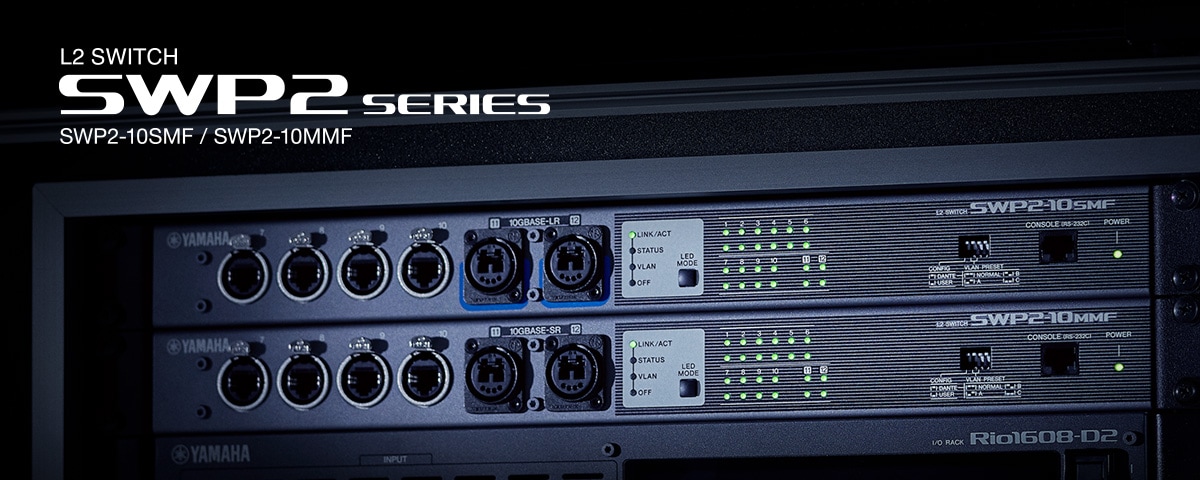
SWP2-10MMF has two fiber ports (opticalCON multimode), while SWP2-10SMF has two fiber ports (opticalCON singlemode).
Can single-mode fiber modules be installed?
Single-mode fiber modules can be installed to SWP2-10SMF but not to SWP2-10MMF.
What does the “STATUS” LED mode show?
Each LED will light or blink when a loop is detected on the port. If there is no loop, the LEDs will be off.
What does the “VLAN” LED mode show?
The LEDs are used to indicate the VLAN assignment for each port. For example, if both LEDs are unlit, the port is assigned to VLAN 1. VLAN2 is shown by only the upper LED being lit green, while VLAN3 is shown by an orange upper LED. If both LEDs are lit orange, it indicates that the port is used as a Trunk.
What is the CONSOLE RJ45 connector used for?
It is provided for trained IT engineers to use: it is not necessary for normal use. It provides a Command Line Interface (CLI) to manage and configure the switch via serial cable. However, for quick setup, the front panel DIP switches can be used, while a web browser interface provides a convenient additional way to access the switch settings.
I cannot initialize SWP2 even if I turn on the SWP2 power while holding down the LED MODE button.
SWP2 series switches cannot be initialized in the same way as SWP1. You can initialize SWP2 by using Web GUI or CLI. For more information, refer to the SWP2's Owner's Manual.
Can I connect the SWP2 and SWP1 via the fiber ports?
No, you cannot. The devices can be connected each other if they have the same transmission system. SWP2-10MMF and SWP2-10SMF are compatible with 10GBASE-SR and 10GBASE-LR respectively while SWP1 is compatible with 1000BASE-SX.
What kind of cable should I use for the SWP2's fiber ports? And how long can I wire the cable when using the SWP2's fiber ports?
The SWP2-10MMF supports GI-type multi-mode fiber cables with a core diameter of approximately 50μm and cladding diameter of approximately 125μm. The maximum length between devices is 300 m.
The SWP2-10SMF supports SM-type single-mode fiber cables with a core diameter of approximately 9μm and a cladding diameter of approximately 125μm. The maximum length between devices is 10 km.
Configuration
What is the difference between the “DANTE” and “USER” Config modes?
The "DANTE" mode is already optimized for use with a Dante audio network. In other words, the settings such as EEE, QoS, and IGMP Snooping are automatically set for Dante. Use “DANTE” mode in combination with the “VLAN PRESETS” to recall a convenient configuration. These are factory presets, which will be recalled after each reboot.
The "USER" mode memorizes the switch settings, which can be freely edited. For example, use a DANTE VLAN PRESET to begin, export the Config file, switch to USER mode, load the Config file, then edit the VLAN assignments. These settings will be memorized, even after power-off.
Please note that DANTE and USER are completely different modes. Not only the switch configurations, but also the other settings such as administrator password and IP address, are not shared between them.
How many VLANs are supported by the switch?
Up to 255 VLAN IDs between 2 to 4094 except for default VLAN1 can be defined.
Can any of the RJ45 ports be used as a “Trunk”, or only the fiber ports?
VLAN PRESET B uses two etherCON/RJ45 ports as “Trunk” ports, as well as the fiber ports. With the USER CONFIG, any port can be used as a “Trunk”.
Can 2 cables be used between a pair of switches to provide a doubled network bandwidth and a redundant connection?
Yes, Link Aggregation is provided with VLAN Preset Normal, A and B. However, this type of redundancy does cause short audio dropouts in the Dante network after a cable failure, so it is recommended to use separate Primary and Secondary Dante networks in critical applications. You can also use Link Aggregation on each separate Primary and Secondary network.
How can a user modify the switch settings, program VLANs etc?
Use the Web GUI, which is accessed via the Yamaha LAN Monitor software.
How can I use Spanning Tree for a redundant ring network?
The VLAN PRESETS are not suitable for use in a Spanning Tree network, though they can be edited via the Command Line Interface (CLI) to support Spanning Tree.
Can the SWP2 and SWP1 be used in combination with other makes of switch?
Yes, though it is recommended to use Yamaha switches throughout the network for a more stable environment and better network monitoring facilities. Features such as Link Aggregation and Spanning Tree might not be fully compatible with other makes of switch.
Feature-set
Does the switch support EEE (“Energy Efficient Ethernet”)?
Yes, though it is disabled in DANTE CONFIG mode for stable Dante networking.
Does the switch support QoS with DSCP?
Yes. It is set up correctly for use with Dante in DANTE CONFIG mode.
Does the switch provide IGMP Snooping (V3) for filtering multicast traffic?
Yes. It is enabled in DANTE CONFIG mode. However, note that it is disabled on VLAN 2 of Preset A and B, because VLAN 1 is designed for a Dante network while VLAN 2 is for other network data on these presets.
Can the switch be the IGMP Querier?
Yes. It is enabled on the VLANs set up for Dante in DANTE CONFIG mode. If multiple units of SWP2 and SWP1 series are connected, one of them will be automatically elected as the Querier.
Does the switch protect against network loops?
Yes. If any loop is discovered, it will be automatically blocked.
Does the switch have a static IP address for management purposes?
The switch is set to DHCP by default. In a Dante network without a DHCP server, it will default to using an IP address in the range 169.254.*.*. In the same way as Dante devices, the switch does not rely upon IP addresses to be discovered by the management software (Yamaha LAN Monitor). A static IP address can be assigned to the switch if required.
What security settings does the switch have?
The Web GUI can be protected by a password, to stop unauthorized changes to the settings.
Are there any extra security functions to protect additional devices being added to the network?
Port Shutdown, ACL (Access Control List) and port authentication are available to protect from unwanted access.
Yamaha LAN Monitor
Which switches can be used with this software?
SWP2, SWP1, SWR and SWX series are the main focus for this software. Some other Yamaha switches, router, and wireless AP are also supported, but with limited functionality. Some 3rd party switches will be discovered, but will not be controlled.
How does the software discover the switches in the network?
A Layer 2 protocol is used, without any need to take care of the IP addresses. Just select the correct network interface on your computer, then the switches and Dante devices will be discovered automatically.
Can the software be used to configure switch settings?
Not directly. This software is primarily used for network monitoring. However, the software does include a short-cut to access the Web GUI, which is used for editing the switch settings.
Can each switch be given a name for easy recognition?
Yes, they can be named in the “Device Settings” of Yamaha LAN Monitor.
Can USER switch config settings be saved and loaded into other switches of the same type?
Yes, this can be achieved via the Web GUI.
Can any programming or editing be made off-line?
Not easily. The only chance is to save the switch config as a .txt file and edit that. Only experienced programmers should attempt that.
Can the software be used to edit settings in Dante devices?
No, just monitoring Dante settings such as bandwidth used, latency, and sample-rate. Dante Controller software can be used on the same computer for editing Dante device settings.
Can a log file be saved for trouble-shooting purpose?
Yes, a SYSLOG can be output from each switch and saved via the Web GUI.
Why do some Dante devices have 2 different MAC addresses and register 2 times in the “Connected Devices” list?
Some Dante enabled devices such as Yamaha CL-series, QL-series and R-series register twice in the Connected Devices list of Yamaha LAN Monitor. This is normal behavior, as these devices have 2 MAC addresses: one for the Dante port and one for device management.
What is the “Snapshots” function used for?
Press the “Snapshot” icon to remember the current status of the connected devices. If the status changes at all (if a new device joins the network or if a device leaves the network), the software will notify the user. A new device will be highlighted blue, while a missing device will be highlighted red. That would make troubleshooting quick and easy. If you reconfigure the network, press the Snapshot icon once again to reset the reference.
MCP1 controllers do not appear in the “Connected Devices” list.
Start Yamaha MTX-MRX Editor software, or send a PING command to MCP1 and press the Update button in the Connected Devices list of Yamaha LAN monitor. MCP1 will be discovered and displayed.
Web GUI
What is the initial user name and password for logging in to the switch via Web GUI?
A user name and password for logging in to the switch via Web GUI are not set.
Why is the Web GUI sometimes not able to change the VLAN settings of specific ports?
This is because those ports will be assigned to a Link Aggregation group, and the Web GUI does not currently support the editing of Link Aggregation groups. In this case, disable the group by using the Command Line Interface, then change the VLAN settings via the Web GUI.
The SWP1 does not maintain the clock time during power-off, therefore the day and time setting will be initialized whenever it is restarted. How about the SWP2?
The SWP2 maintains the clock time during power-of by itself. If you want to keep the time more precisely, use an NTP server and set SWP2 as its client.
RADIUS server function
What is the RADIUS server function?
RADIUS (Remote Authentication Dial-In User Service) is one of the networking protocols for user authentication. A RADIUS authentication system consists of three elements: a RADIUS server, RADIUS client, and users. A RADIUS client transfers a user's information to a RADIUS server as the client receives a user authentication request to access. In response to the authentication request, a RADIUS server authenticates and decides to allow access by the user. By using the switch's RADIUS server function, an authentication feature can be used without an additional RADIUS server.
What other authentication methods can be used with the RADIUS server function?
Mac authentication, Web authentication, and IEEE802.1X authentication can be used with the RADIUS server function. They can be used together by setting them to each port.
Which port can be connected to use the authentication function?
Any port can be used but make sure to enable the authentication function of a port to be connected to use the authentication function. And an authorized device can communicate via the port.
How can a system with multiple switches be configured?
Set all the switches as a RADIUS client and set the RADIUS server functions to one of the switches. Registering device information to be authorized to the server will connect to the server.
Can the RADIUS server function be used with one switch?
Yes. Set the RADIUS server function and the client function.
Which switches support the RADIUS server function?
The following L2 intelligent series switches support the RADIUS server function: SWR2311P-10G, SWR2310, SWP2 and SWX series.